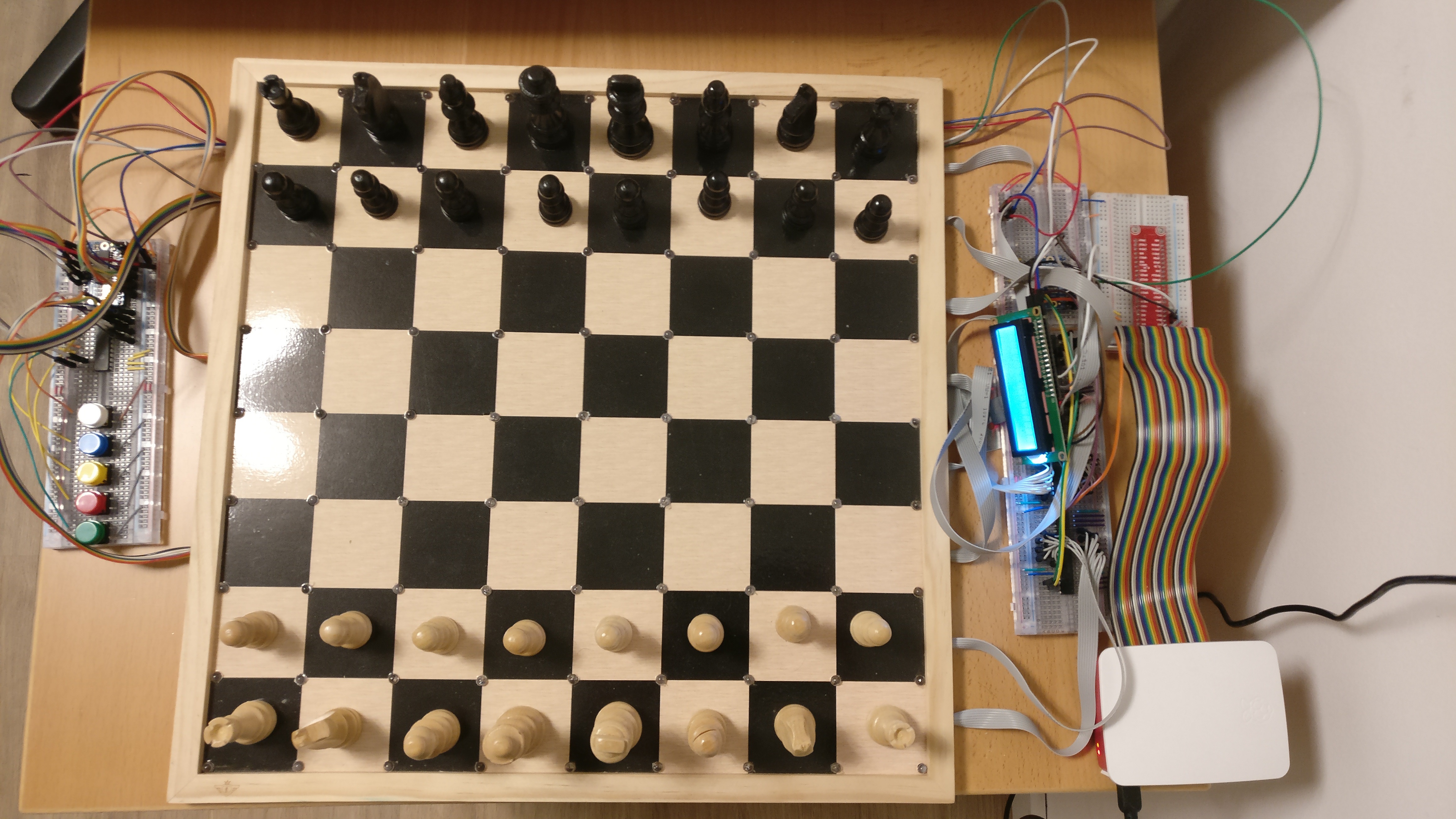
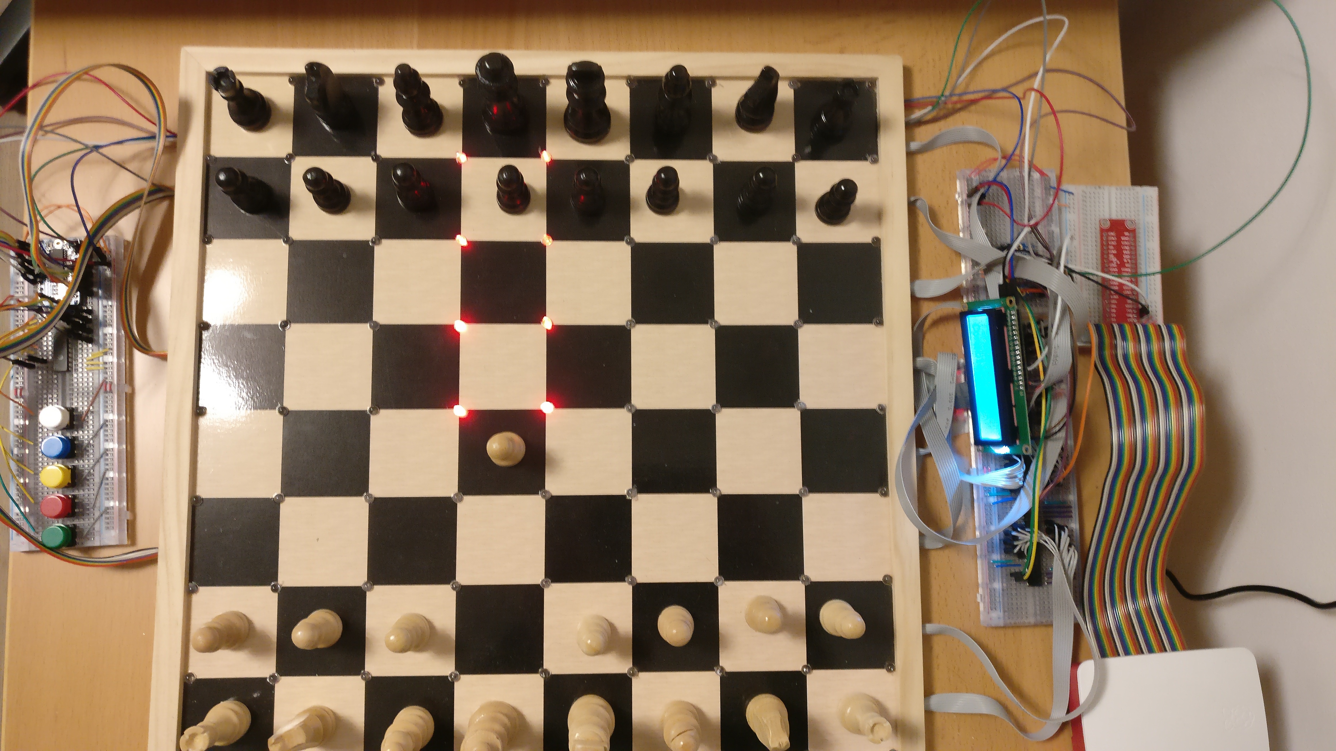
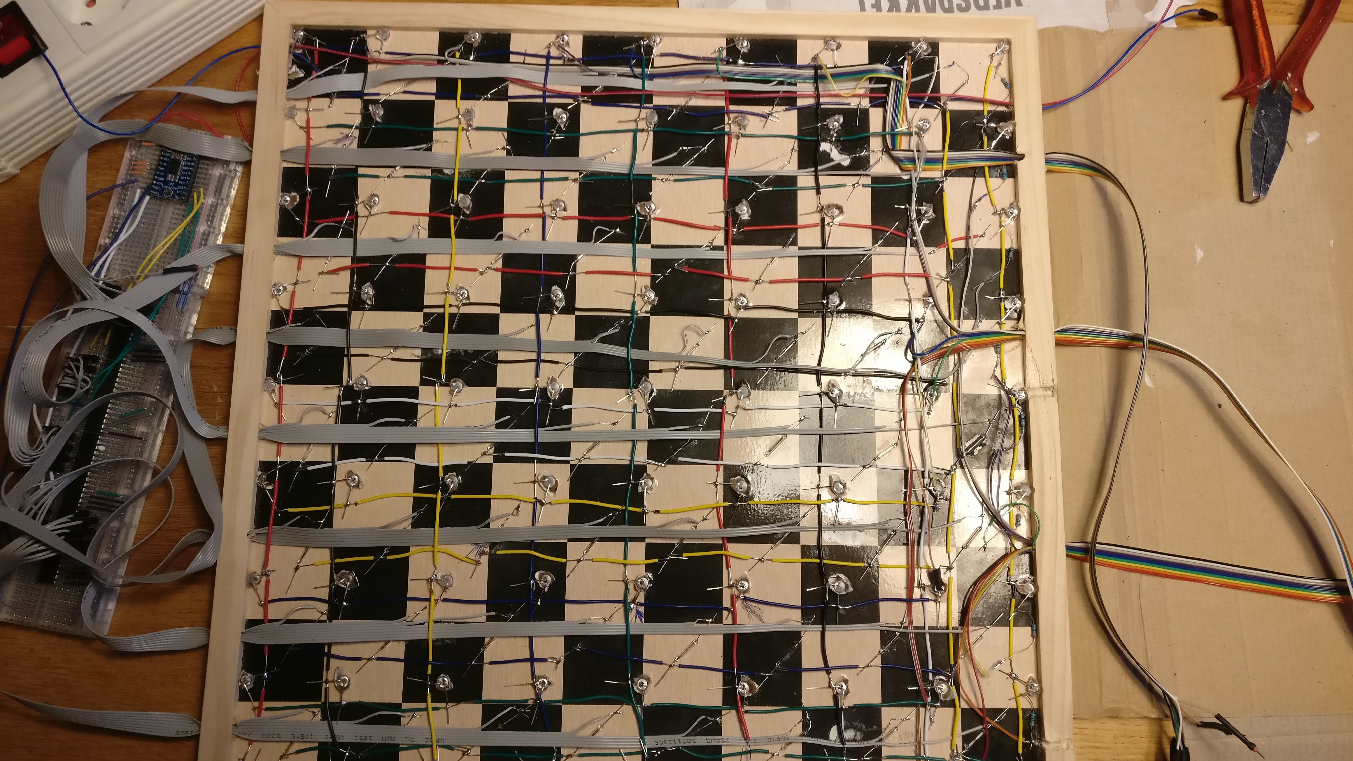
Hardware description
There are various ways to create the hardware for a smart chess board and the software will work with any implementation. This page we outline the hardware implementation used in the original project. In the original project it is detected if a square is occupied using reed switches. Reed switches close when a magnet is in its vicinity. We can detect pieces by putting a magnet in every piece and a reed switch below every square. When a square is occupied then the reed switch will close. This will close a circuit which we can use to detect the piece. We can track how pieces move over the board by detecting when squares become empty and when they become occupied. There is one problem, we cannot just connect 64 reed switches (and 64 LEDs) to a controller. This is where the I2C bus comes in. The I2C bus allows us to theoretically connect an infinite amount of devices using only 4 cables:
Power
Ground
SDA (Digital messages to all devices)
SDL (The clock of the controller)
We cannot directly connect analog signals from the reed switches and LEDs to the I2C bus. Instead of this we need components which convert digital signals to analog signals. There are a lot of different cheap components readily available. I have used the Adafruit HT33K16 matrix driver to control most of the LED and and 5 MCP23017 to control a few remaining LEDs and all reed switches. The MCP23017 are very useful components which can be controlled over the I2C bus. The MCP23017 has 16 analog channels which can both read input and send output. Note that brandless MCP23017 are available and a lot cheaper. My hardware design is largely based on the design suggested here This site contains a very extensive explanation of the hardware design. In the remainder of this section I will only briefly discuss some important observations and some changes I made to the hardware design.
Noisy bus problem
One problem you will most likely encounter is noise. Noise is when messages on the bus get send but get corrupted on the way. If many devices are connected to the I2C bus they might be sending messages at the same time. When two devices send a message at the same time then the messages can collide and both messages might become corrupted. This will result in a software error. Because the many devices will be connected to the bus these collisions are likely to occur. Next to this the magnets can also create noise. A very useful components is the TCA9548A I2C Multiplexer. This device allows us to split one I2C channel into 8 channels which prevents collisions. However there is one very annoying bug in the library of this device. If you use the adafruit library then the multiplexer will softlock if an exception is thrown. You can prevent this by setting the variable tca.i2c._locked to False after an exception is thrown, ie:
import board
import busio
import digitalio
import adafruit_tca9548a

i2c = busio.I2C(board.SCL, board.SDA)
tca = adafruit_tca9548a.TCA9548A(i2c)
some_device = some_device(i2c = tca[0], address = 0x20) # device connected to channel 0 at address 0x20
try:
    seme_device.do_something()
except OSError:
    i2c.tca._locked = False
Hardware improvements
All components will need to be connected. There are two kinds of wires which can be used, single core wire and stranded wire. Single core wire is a lot easier to handle and solder but it is not flexible. Stranded wire is very flexible and cheap but a lot harder to wire. To connect all components under the board you need to use single core wire. Connecting the chess board to the breadboards can be done using stranded wire. In my project I have connected these wires to a breadboard. Because of this I have manually soldered pins on the end of every wire. I do not recommend doing this. While it is slightly cheaper to solder every pin to a stranded wire this takes a lot of time time and the connections are a common cause of failure. In hindsight I recommend stripping male to male jumper cables. This is slightly more expensive but at least the cables will stay put and they will have strong pins. The large amount of soldering and connections and the noise on the I2C bus are the main problems with the current hardware design. However there is one possible improve to mitigate these problems.
The LEDs are wired to the LED matrix driver using a clever trick. The LEDs are wired as a matrix. This means that the plus pins of the LEDs in one file are all connected to the same wire and that the minus pins of all LEDs in one rank are wired together. When all LEDs are off then the matrix driver will keep all connections open. This means that there is no power on any plus pin and no minus pin is connected to the ground. The matrix driver can turn on an LED by closing the switches corresponding to the rank and file. No other LEDs will turn because no other LED will have both a connected plus and minus pin. The matrix driver can turn on multiple LEDs on one file by opening multiple ranks. We cannot also turn on LEDs at other files since unintended LEDs will light up. The matrix driver solves this by turning on the files one by one and just blinking all LEDs faster then the human eye can see. This is called scanning.
Wiring the LEDs in a matrix form is great because it requires a lot less connections and it only uses one bus device. The matrix driver can connect 124 wires using only 24 connections. Since the large amount of connections and the large load on the I2C bus where the major problems with the hardware design wiring components in a matrix can significantly improve our design. In the original design the reed switches were all just wired one pin of the MCP23017 per reed switch. Because of this we needed a lot of MCPs and a lot of connections. However since the MCP23017 can both give output and read input the reed switches could also be wired in a matrix. Every file of reed switches should be wired to one output pin of the MCP and every row of reed switches to an input pin. By turning on only one output pin and reading the output pins we can get the occupancy of one file. We can now scan the chess board by scanning the board file by file. Since one MCP23017 has 16 channels this new design would only require one MCP and one matrix driver. It is unlikely that a TCA9548A is needed. This new design saves a lot of money and time and next to that it even has less points of failure.
As a last footnote I want to mention that I used 4 LED to mark a square for aesthetic reasons. While this is most certainly possible it does add a large amount of extra work. While the change seems minor this added 17 extra LED and one whole extra MCP which needed resistors. Using a 9 by 9 LED matrix is certainly possible but be aware of the large amount of extra work that is needed
Hardware used
In this section picture of the hardware can be found and a list of all used components. Note that the list includes components with a link to the official Adafruit site. These products will be cheaper at your local retailer. The Adafruit libraries are great and I recommend using them however not all third party tools are compatible with them. The matrix backpack, the multiplexer and the LCD backpack need to be bought from Adafruit to use the library. Every other component can be brandless.
Component |
Amount |
1 |
|
1 |
|
5 |
|
1 |
|
1 |
|
1 |
|
5 |
|
Chess set 40 cm |
1 |
Reed switch normally open |
64 |
LEDs 5v |
81 |
Neodymium magnet |
32 |
Resistor 330 ohm |
9 |
Pins header male to male |
80 |
Wires and breadboard |
Lots |


